RV Jet - Wiring, Calibrations & Sensor Intergration
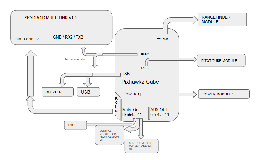
Our RV Jet project begins with determining the wiring diagram. Our group was able to generate a detailed diagram of different components. (Showing as below)
QGroundControl is the ground station we have decided to use during this class.
During our firmware workshop, The primary firmware Ardupilot is somehow malfunctioning, and we end up using the PX4 as our solution.
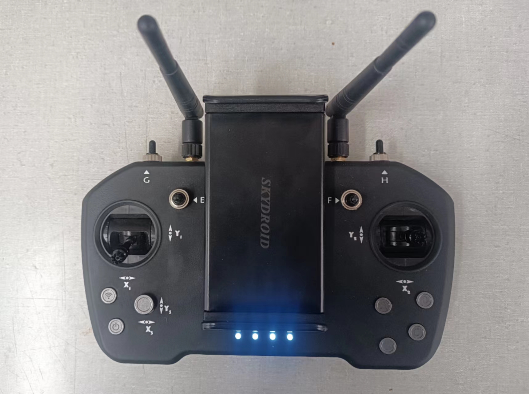
The Skydroid TI12 is our primary controller for the RV Jet, Frequency matched with the aircraft during our lab. (Controller shown below)
To set up and calibrate the compass on the RV Jet, On the first several attempts, the software will have errors pop out during our calibration, sometimes it stops halfway, or when we completed, the failure page will appear, we end up being able to calibrate completely. The errors may be due to metal components inside COMP101.

In the next step, we work on setting up and calibrating the pitot tube as well as the airspeed indicator. SENS_EN_SDP3x & ASPD_PRIMARY parameter was activated. Pressure and some airflow need to be detected by the pitot tube in order for it to collect data properly. We have one of our teammates blow airflow hard toward the tube. The system was set up completely afterward.

Some notes about our LiDar setup:
LiDar is the visual sensor attached to the bottom of the RV Jet. Our LiDar component will not connect properly to our LightWare software, even after we attempt on switching wires Or switching aircraft devices. The professor indicated malfunctioning, we will need a new part to install if possible.


Comments
Post a Comment